I built a grid sequencer as my final project for MIT 6.115, a class on microcontrollers and embedded systems. My goal was to bring a creative embedded software project from concept to fully-functional prototype. You can find demo videos of my sequencer below.
Watch Percussion Demo on YouTube
The Idea
Grid instruments, like the Novation Launchpad, are often used in electronic music production to create looping patterns of sounds. A simple one works like this:

In the grid, rows represent different sounds, and columns represent different times. The user toggles buttons to indicate which sounds should be played and when. The sequencer cycles through the columns in order, playing the selected sounds as it arrives at each column.
Setting Up the Button Pad
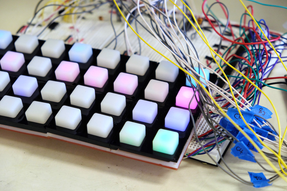
To assemble a grid with 4 rows and 8 columns, I bought 2 SparkFun 4x4 button pads, the corresponding breakout PCBs and bezels, and 3mm common anode RGB LEDs.
Setting up 32 buttons and LEDs, even in a matrix arrangement, required a lot of soldering. (At the end, my 4x8 button pad had 32 wires coming out of it!)


The front and back of the button pad breakout PCB. (SparkFun)

It was hard to cut wires to the perfect length between the two boards.
Grid Software Interface
After assembling my grid controller, I set up a software interface for it. 6.115 supplied each student with a PSoC board, which is like an instant chip inventory. In PSoC Creator, I could configure pins on the board to act like a variety of chips and reassign pins easily.
The software interface involved (1) matrix scanning to detect button presses and (2) updating the LED matrix to reflect grid state.
Detecting Button Presses
When the buttons on the pad are pressed, conductive circles underneath them make contact with the circles on the breakout PCB.
To detect a button press, I cycled through the rows one at a time. For each row, I drove the target row HIGH and the other rows LOW, and then read in the output of all the columns. If a column was also HIGH, then I knew the button at that row and column was currently being held down.

A scope screenshot of a button press.
I maintained two 2D arrays: one for transient button state, and one for the persistent grid state. I used the first array to detect key-up events (when a user lets go of a button) and toggle the corresponding value in the second array.
Driving LEDs
If I connected all 32 wires to analog PSoC pins, I could set my LEDs to any RGB color, but:
- Because the PSoC couldn't source enough current to drive all the LEDs, I brought in LM293 push/pull drivers. These drivers work with digital inputs and outputs, so I reconfigured my RGB lines as digital, limiting myself to 7 possible colors.
- The PSoC has limited GPIO pins, and I wanted to save those for other purposes.
To keep things simple and compatible with the drivers, I designated one color per row: turquoise (0% R 100% G 100% B), pink (100% R 0% G 100% B), blue, and green. For turquoise and pink, I connected two color wires to the same driver output so that I could control them both at the same time. This setup saved me 8 PSoC pins.
I made liberal use of C's shift and bitwise logic operators to match the LEDs to a 2D array representing the grid state.
Now, I have a grid controller that turns on an LED when I press the corresponding button!
Playing Audio
The next step was to get my PSoC to play audio. Originally, I wanted to play 16-bit 44.1 kHz WAV drum samples using an external RAM chip. After wiring up the chip, I realized, how am I supposed to transfer such a large amount of audio data onto the RAM every time the program starts up?
Converting WAV files to C arrays and putting them into code memory didn't seem feasible, because the PSoC internal memory was limited. I tried burning them onto a ROM chip, but I ran into unknown errors with the lab chip burners. I looked into using serial, but the setup seemed too complex for the timeframe I had.
Soon, I found a much simpler (though hackier) solution. I discovered that PSoC Creator's WaveDAC component allows for custom user-defined tables. If I converted my WAV files to CSV files of 8-bit raw audio data, then WaveDAC could play them!

WaveDAC configuration with a custom table loaded into Waveform 1.
WaveDAC takes a max of 4000 table values, so I downsampled my WAV files to 16 kHz, trimmed and padded them to exactly 0.25 seconds, and removed the WAV metadata and headers. Soon after... my PSoC played drums! (And the 8-bit 16 kHz samples didn't sound bad!)
Timing and Sequencer Logic
The driving force of a grid sequencer is a timer that determines which column is active. I implemented this with a PSoC Timer component and had it generate a software interrupt on overflow. With the max load value, an interrupt was triggered every 2.731 ms.
Every NUM_INTERRUPTS interrupts, the interrupt handler increments the active column, starts the appropriate WaveDAC components, and turns on all LEDs in that column. The result is a "shifting" column of LEDs that shows the sequencer timing.
The tempo is set by the NUM_INTERRUPTS variable:
tempo = 60 / (NUM_INTERRUPTS * 0.002731)The user can control the sequencer tempo by turning the PSoC's onboard potentiometer. I sampled the potentiometer value using a 12-bit PSoC ADC, and then mapped that to the NUM_INTERRUPTS variable. In the following formula, adcResult ranges from 0x0000 to 0x0FFF:
NUM_INTERRUPTS = 400 - (adcResult * 300) / 0x0FFF This gives a NUM_INTERRUPTS range of 100-400, which corresponds to tempos of approximately 220 to 55 columns per minute.
Mixing Audio
One downside of using WaveDAC components is that it's difficult to manipulate their outputs in code — I couldn't sum the outputs of multiple WaveDAC components to play multiple sounds at once.

An analog mixer example. (Jacob Smith)
I decided to build an analog mixer instead, following this tutorial by Jacob Smith. This added the bonus feature of being able to adjust relative volumes of sounds using potentiometers.
PSoC Creator Schematic

My final PSoC Creator schematic. (full code here)
What I Learned
This project taught me the value of being flexible. Coming in, I had minimal experience with C programming or PSoC Creator, and I wasn't sure how to implement most of my ideas. Many times, the implementations I'd guessed didn't work out, and I learned a lot through rapidly exploring alternative strategies.
Overall, 6.115 has made me more confident in my ability to envision and develop embedded software projects. In the many long hours I've invested into this class, I've gained fluency with design patterns, working with lab equipment, reading data sheets, and integrating various types of chips into a system. And I had fun playing around with my finished grid sequencer.
What's Next
I especially found the audio aspects of the project — picking apart WAV files and manipulating them as data — quite fascinating. I'd like to explore that in more depth in the future. I'm also interested in MIDI and electronics — I wonder what it takes to build a grid sequencer with MIDI-compliant output.

My finished sequencer: grid controller, breadboard, and PSoC. Speaker not pictured.
| tags | Electronics · Embedded Systems · Music Technology |
| technologies | PSoC · C · Button Pad · LEDs · Speaker |
| context | MIT 6.115 Microcomputer Project Laboratory |
| completed | May 2019 |